S7 In-Line Signal Conditioning Amplifiers |
| | | |||||||
| ||||||||
| Signal conditioning is required where the output of a transducer needs to be boosted or changed into a form suitable for the monitor or logging device which will be used. These amplifiers are suitable for LVDT transducers, strain gauge sensors and some internally amplified transducers. Our S7 amplifiers are specifically designed to be installed close to the transducer so that the signal can be boosted as soon as possible. The S7 signal conditioning units are mounted in a die-cast aluminium housing and have a good level of environmental protection and screening from electrical noise. A very wide range of gain adjustment ensures that our amplifiers are compatible with the vast majority of LVDT and strain gauge sensors available from any manufacturer. There are several versions with different input, output and transducer compatibility. |
| S7AC dc powered LVDT transducer amplifier. | |||||||||||||||||||||||||||
| |||||||||||||||||||||||||||
| Compatible with | Any standard RDP LVDT LIN & PY When fitted with two 1k Ohm bridge completion resistors ( Does not provide analogue voltage linearisation for PY) Most LVDTs from any manufacturer | ||||||||||||||||||||||||||
|---|---|---|---|---|---|---|---|---|---|---|---|---|---|---|---|---|---|---|---|---|---|---|---|---|---|---|---|
| Supply voltage (single, must be floating) | 12V to 36V dc, 50mA | Output ripple | 5mV peak-to-peak typical / 10uA peak-to-peak typical | ||||||||||||||||||||||||
| Supply voltage (dual) | ±6V to ±18V dc, 50mA | Input impedance | ±130k Ohms | ||||||||||||||||||||||||
| Transducer excitation | 1V, 5kHz (1kHz to 10kHz with component change), 25mA | Temperature coefficient (zero) | ±0.003% F.S. /°F minimum | ||||||||||||||||||||||||
| Output details | ±4V to ±10V (may be affected by supply voltage) / 4-20mA (loop resistance 100 Ohms to 550 Ohms) | Temperature coefficient (span) | ±0.006% F.S. /°F minimum | ||||||||||||||||||||||||
| Amplifier gain range | 0.07 to 500 | Approximate zero adjustment range | ±5V | ||||||||||||||||||||||||
| Signal input range | 30mV to 4V | Operating temperature range | 14°F to 140°F | ||||||||||||||||||||||||
| Linearity error | ±0.1% F.S. | Total weight | 9.2oz | ||||||||||||||||||||||||
| Electrical output bandwidth | 0 to 500Hz | Cable gland cable size | 0.12'' to 0.26'' | ||||||||||||||||||||||||
| S7TW 4-20mA loop powered LVDT transducer amplifier. | |||||||||||||||||||||||||||
| |||||||||||||||||||||||||||
| Compatible with | All standard RDP LVDT transducers except the following which require a free of charge modification called TM0202 D5/25, ACT2000, ACT2000A, ACT2000C, ACT4000, ACT4000C, ACT15000C, ACT18500C Most LVDTs from any manufacturer | ||||||||||||||||||||||||||
|---|---|---|---|---|---|---|---|---|---|---|---|---|---|---|---|---|---|---|---|---|---|---|---|---|---|---|---|
| Supply voltage | 12V to 36V dc | Output ripple | 50uApeak-to-peak (15uApeak-to-peak with filter turned on) | ||||||||||||||||||||||||
| LVDT minimum input impedance | 130 Ohms | Input impedance | 100k Ohms | ||||||||||||||||||||||||
| Transducer excitation | 0.5V (4mA), 5kHz | Temperature coefficient (zero) | ±0.003% F.S. /°F (typical) | ||||||||||||||||||||||||
| Output details | 4-20mA (loop resistance 50 Ohms to 1.2k Ohms maximum) | Temperature coefficient (span) | ±0.008% F.S. /°F (typical) | ||||||||||||||||||||||||
| Amplifier gain range | 2.5 to 333 | Approximate zero adjustment range | ±8mA | ||||||||||||||||||||||||
| Signal input range | 30mV to 4V | Operating temperature range | -4°F to 185°F maximum | ||||||||||||||||||||||||
| Linearity error | ±0.05% F.S. | Total weight | 1.2lb | ||||||||||||||||||||||||
| Electrical output bandwidth | 0 to 250Hz (25Hz with filter turned on) | Cable gland cable size | 0.12'' to 0.26'' | ||||||||||||||||||||||||
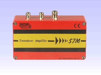
| S7M 115/230V ac powered LVDT transducer amplifier. | |||||||||||||||||||||||||||
| |||||||||||||||||||||||||||
| Compatible with | Any standard RDP LVDT LIN & PY When fitted with two 1k Ohm bridge completion resistors ( Does not provide analogue voltage linearisation for PY) Most LVDTs from any manufacturer | ||||||||||||||||||||||||||
|---|---|---|---|---|---|---|---|---|---|---|---|---|---|---|---|---|---|---|---|---|---|---|---|---|---|---|---|
| Supply voltage | 230V or 115V ac, 2.5VA, 50/60Hz | Input impedance | ±100k Ohms | ||||||||||||||||||||||||
| Transducer excitation | 5V, 5kHz (1kHz to 10kHz with component change), 100mA | Temperature coefficient (zero) | ±0.001% F.S. /°F typical | ||||||||||||||||||||||||
| Output details | ±10V / 4-20mA (loop resistance 0 Ohms to 600 Ohms) | Temperature coefficient (span) | ±0.002% F.S. /°F (typical) | ||||||||||||||||||||||||
| Amplifier gain range | 0.15 to 200 | Approximate zero adjustment range | ±10V | ||||||||||||||||||||||||
| Signal input range | 20mV (minimum) to 20V | Operating temperature range | 14°F to 122°F | ||||||||||||||||||||||||
| Linearity error | ±0.1% F.S. maximum | Total weight | 4.0lb | ||||||||||||||||||||||||
| Electrical output bandwidth | 0 to 500Hz | Cable gland cable size (x2) | 0.12'' to 0.24'' | ||||||||||||||||||||||||
| Output ripple | 5mV peak-to-peak typical | Cable gland cable size (x1) | 0.20'' to 0.39'' | ||||||||||||||||||||||||
| S7DC dc powered strain gauge transducer amplifier. | |||||||||||||||||||||||||||
| |||||||||||||||||||||||||||
| Compatible with | Most full bridge strain gauge transducers | ||||||||||||||||||||||||||
|---|---|---|---|---|---|---|---|---|---|---|---|---|---|---|---|---|---|---|---|---|---|---|---|---|---|---|---|
| Supply voltage (single, must be floating) | 10V to 36V dc, 30mA (plus transducer and output load) | Output ripple | 10mV / 30uA | ||||||||||||||||||||||||
| Supply voltage (dual) | ±5V to ±18V dc, 30mA (plus transducer and output load) | Input impedance | >10M Ohms | ||||||||||||||||||||||||
| Transducer excitation | 3V to 10V , 100mA | Temperature coefficient (zero) | ±0.001% F.S. /°F (typical) | ||||||||||||||||||||||||
| Output details | ±3V to ±10V / 4-20mA (loop resistance 0 Ohms to 800 Ohms) (may be affected by supply voltage) | Temperature coefficient (span) | ±0.002% F.S. /°F (typical) | ||||||||||||||||||||||||
| Amplifier gain range | 1 to 1250 | Approximate zero adjustment range | ±2V | ||||||||||||||||||||||||
| Signal input range | 4mV to 10V | Operating temperature range | -40°F to 185°F maximum | ||||||||||||||||||||||||
| Linearity error | ±0.02% F.S. | Total weight | 9oz | ||||||||||||||||||||||||
| Electrical output bandwidth | 0 to 5kHz (20Hz with filter turned on) | Cable gland cable size | 0.12'' to 0.26'' | ||||||||||||||||||||||||
| S7MZ 115/230V ac powered strain gauge transducer amplifier. | |||||||||||||||||||||||||||
| |||||||||||||||||||||||||||
| Compatible with | Most full bridge strain gauge transducers | ||||||||||||||||||||||||||
|---|---|---|---|---|---|---|---|---|---|---|---|---|---|---|---|---|---|---|---|---|---|---|---|---|---|---|---|
| Supply voltage | 230V or 115V ac, 2.5VA, 50/60Hz | Input impedance | ±1G Ohms | ||||||||||||||||||||||||
| Transducer excitation | 5V, 5kHz (1kHz to 10kHz with component change), 100mA | Temperature coefficient (zero) | ±0.001% F.S. /°F typical | ||||||||||||||||||||||||
| Output details | ±10V / 4-20mA (loop resistance 0 Ohms to 600 Ohms) | Temperature coefficient (span) | ±0.002% F.S. /°F (typical) | ||||||||||||||||||||||||
| Amplifier gain range | 5 to 7000 | Approximate zero adjustment range | ±10V | ||||||||||||||||||||||||
| Signal input range | 1.5mV to 600mv | Operating temperature range | 14°F to 122°F | ||||||||||||||||||||||||
| Linearity error | ±0.1% F.S. | Total weight | 4.0lb | ||||||||||||||||||||||||
| Electrical output bandwidth | 0 to 500Hz | Cable gland cable size (x2) | 0.12'' to 0.24'' | ||||||||||||||||||||||||
| Output ripple | 5mV | Cable gland cable size (x1) | 0.20'' to 0.39'' | ||||||||||||||||||||||||
| S7CT Amplifier for use with RDP capacitive transducers. | |||||||||||||||||||||||||||
| |||||||||||||||||||||||||||
| Compatible with | Sensagap, RCDT, & MLP MCL (S7CT+PD1499) | ||||||||||||||||||||||||||
|---|---|---|---|---|---|---|---|---|---|---|---|---|---|---|---|---|---|---|---|---|---|---|---|---|---|---|---|
| Supply voltage (specify with order) | S7CT = 115/230Vac (±20%) , 6VA S7CTDC = 5/12/24Vdc (±10%) , 3VA | Output ripple | 5mV peak-to-peak typical | ||||||||||||||||||||||||
| Transducer excitation | 15V, 12mA | Input impedance | ±200k ohms | ||||||||||||||||||||||||
| Output details | ±10V / 4-20mA (loop resistance 0 Ohms to 400 Ohms) | Temperature coefficient (zero) | ±0.002% F.S. /°F (typical) | ||||||||||||||||||||||||
| Voltage free relay contacts | 2 | Temperature coefficient (span) | ±0.002% F.S. /°F (typical) | ||||||||||||||||||||||||
| Amplifier gain range | 1 to 35 | Approximate zero adjustment range | ±4V | ||||||||||||||||||||||||
| Signal input range | 300mV to 10V | Operating temperature range | 14°F to 131°F | ||||||||||||||||||||||||
| Linearity error | ±0.02% F.S. typical | Total weight | 1.2lb | ||||||||||||||||||||||||
| Electrical output bandwidth | (0 to 600Hz) to (0 to 60Hz) depending on gain | Cable gland cable size | 0.12'' to 0.26'' | ||||||||||||||||||||||||
| ||||
| Due to our policy of on-going development, specifications may change without notice. Any modification may affect some or all of the specifications for our equipment. | ||||
| RDP Electrosense 2216 Pottstown Pike Pottstown, PA 19465 USA Tel: 610-469-0850 Tel: 800-334-5838 Fax: 610-469-0852 Email: info@rdpe.com | - | |||